Article #10: PUMP-OUT VANES
This article came out
in response to a question from our reader:
Could you explain how an ANSI pump impeller clearance (both open
vane impeller with back pump out vane and reverse vane impeller with balancing holes)
setting affect pump performance? What are the advantages and disadvantages of
these impellers?
The main reason to
use pump-out vanes (POV) is to change the pump axial hydraulic thrust. Take a
look at the picture:
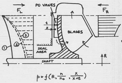
The rotation of the
impeller results in “dragging into rotation” of the fluid in the gap between
the impeller and casing walls. This is similar to a motion of a teaspoon in a
cup, or a disk spinning inside containment. The resulting motion is referred to
as “forced vortex”. Such vortex sets-in in the front and back gaps – between
the casing walls and the impeller front (shown on the right) and a back hub
(shown on the left). The pressure distribution in the gap is parabolic – higher
at the impeller OD, and gradually reducing towards the shaft centerline.
Pressure time area is
force – which is exerted on the impeller from both sides (FR and FL).
The difference between these forces is hydraulic axial thrust, which is
ultimately transmitted to the bearings, and thus is desirable to be small. This
pressure at a given position in a gap depends on the radius, rotational speed
of the fluid (divided by the impeller rotational speed), and the gap.
Curve (1) shows the
static pressure distribution behind the impeller hub without the pump-out vanes.
As we know from basic hydraulics, - the faster the fluid moves, the lower the
static pressure is. So, if we could make the fluid in the gap to rotate faster,
the static pressure would be reduced, and the force FL to become
smaller – closer, and hopeful equal to the FR – to reduce, or
eliminate the net thrust.
Without the POV, the
fluid in the gap is rotated only by the friction (drag) of the impeller hub
wall. It rotates with the same speed as the impeller right at the impeller wall
surface, but (so called “no-slip-condition”) is not rotating at the casing
wall, since that wall is stationary. Thus, on the average, the bulk of the
fluid in the gap is spinning at the angular velocity equal to half
of the angular velocity of the impeller.
But, if we add the
POV, the fluid becomes “trapped” within the POV space, and thus rotates with
the same speed as the impeller – i.e. double of what the fluid does in the
absence of the POV. This, of course, assuming the gap between the POV and the
casing wall is (theoretically) zero (x=0). The number of the POVs actually does
not have to be equal to the number of the impeller main blades, but often is,
due to casting production process, for simplicity.
Obviously, the gap
“x” can not be zero, so the actual reduction of the pressure profile (curve
marked as “2”, is less, depending on the gap “x”. And, if this gap becomes too
large, the effect of the POV diminishes, and eventually disappears. It turns
out that, the POV are most effective at x=0, and become completely non-effective
when x=t, i.e. when the liquid gap (x) becomes equal to the height
of the pump-out vanes (t). (Papers are written on this subject, such as
Zanker’s, explaining whys and whats, and those of you who have a couple of
sleepless nights to study them – let us know, and we will get you the
material).
The balancing holes
are also used to reduce pressure distribution, i.e. a similar idea as the
pump-out vanes. In fact, this is why they are called “balancing”. To be
effective, the impeller must have a tight clearance between it and a casing
(not shown on a picture above), to separate the higher pressure zone, from a
lower pressure zone. The balancing holes thus connect the back of the impeller
with the inlet area, where pressure is low (close to suction). Some leakage
will occur, reducing the efficiency. If there is no clearance, such as shown
above, the leakage will be greater, reducing the efficiency even more.
Another reason for
the POV is to reduce the pressure at the mechanical seal area. The effect of
these vanes can be very strong, and, sometimes even result in creating vacuum,
and boiling out of the liquid. This could be trouble, as mechanical seals do
not like to operate in a vapor environment.
Regarding the
performance – there is price to pay for the thrust balance, as the additional
power required to spin the liquid faster takes away the efficiency. This is
why, the higher energy pumps, such as API, or boiler feed, rarely have the
pump-out vanes, while the ANSI pumps, which are relatively lower horsepower
units, have these.
Note the picture
above shows an open impeller. The front gap, between the
impeller and the casing, must be tight (typically 0.015 – 0.030”, depending on a
pump size). The challenge is thus to maintain both front and back gaps small –
from the efficiency and thrust standpoint. Close impellers solve
this problem, but at the expense of reduced ability to handle stringy, such as
fibrous, solids.
And finally, regarding
the “reverse vane impeller”. The impeller shown above is a standard design,
such as, for example, manufactured by Goulds, model 3196. To adjust the front
clearance, the rotor must be pushed against the casing, and then backed-off by
the amount of design clearance. It is sometimes desirable to keep the casing
piped-up, as it is somewhat a chore to re-pipe it. This requires re-setting of
the front gap, during maintenance, on site – and, if it rains or snows – you
freeze and catch a cold!
If the impeller is
“turned around”, such that the clearance gap is between the impeller and the
stuffing box (or a sealing chamber), then this clearance can be set at the
shop, and the rotor can then be simply brought to a casing and bolted on
quickly. Example of such design is former Durco Mark III design.
As you can see, each
design option has advantages, and disadvantages, and the ultimate decision
remains with a specific application requirements.
We welcome your comments to: