Article #26: Proper
Pump Piping Procedure – 10 steps
By
Dr. Lev Nelik, P.E., APICS
Pumping Machinery, LLC
It
should be realized that piping issues directly affect the pump’s life and its
performance. Bringing the pump to the
pipe in one operation and expecting a good pump flange or vessel fit is a very
difficult, if not impossible, task. When
bringing the pipe to the pump the last spool (suction side and discharge side,
each) should always be left until the pump has been leveled in placed and rough
aligned. The final alignment will be a
“free bolt condition”, and, as may sound like a surprise to some, no “come-alongs”
would be needed. As an ultimate investement in common sense and proper
attention to details, - your pumps will last longer, with fewer failures of
seals, shafts, bearings and couplings. More equipment uptime, and less lost
production, will result in significant savings in dollars, and fewer headaches.
Step 1 (only for cases where there is
NO thermal growth – otherwise see Step 2 discussion)
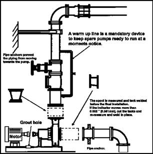
At
this point the pipe should be securely anchored just before the last spool, to
prevent future growth towards the pumps flanges.
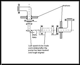
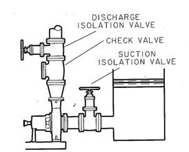
Figure 1 Occasional
usage of “anchors” (only if there is NO thermal growth (which is practice very
rare) for the pump piping – example would be a very short run of suction pipe
connecting it to a cold water tank, which keeps the pipe at essentially
constant (e.g. ambient) temperature, same as water in the tank. In most cases,
however, anchors should not be used (see Step 2 discussion)
The
final piping lay out should not be finalized until certified elevation drawings
are received from the engineering group or from the pump vendor. Once the final certified prints are received
the final isometrics can be completed and the piping takeoff can be done.
The
delivery of the equipment can either be early or it can be late in arriving at
the site. When the equipment is late it
is critical to have certified elevation prints of the equipment. The certified prints that the isometrics
required for the piping takeoffs can be made without impacting the construction
schedule. If the equipment is early, it
will arrive at the site prior to the construction team needing it for
installation. In such cases, early preparations must be made for long term
storage. It is customary to use oil mist
lubrication to keep the equipment in as-shipped conditions during the
storage. The pressurization of the
bearing housing and the casing with just 10 to 20 H2O pressure
prevents moisture and contaminants from entering the sealed areas and damaging
the components. The early delivery of
equipment to the site has the advantage of allowing for verification of the
actual measurements.
Step 2
Once
the location of the equipment is set, the baseplate can be put in place,
leveled and rough-aligned, with the equipment mounted. Rough alignment of the equipment should be
done prior to building the grout forms. To avoid stresses caused by thermal
expansion of pipes, expansion loops should be installed in suction and
discharge lines. The “sliding” pipe supports near pump suction and discharge
are required to eliminate weight loads of piping on them pipe, which can cause
excessive loads and misalignment, leading to seal failures, bearings,
couplings, etc. However, “anchors” (three dimensional restraints) should not be
used, as these could cause significant stresses and casing distortions due to
thermal expansion. Consider, an example (Fig. 2C) of incorrectly placed
“anchor” (restraining growth in ALL directions, i.e. not simply a vertical
“sliding” support), even 2 feet away from the pump suction, and the case where
the pipe expands by only 30 degrees F (morning to afternoon):
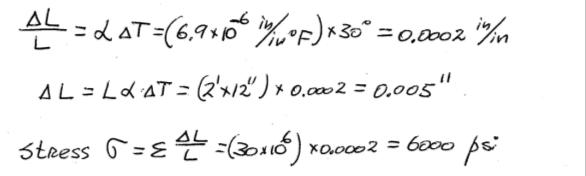
For
the pipe you use, the area of contact between the pump and pipe flanges depends
on the size of the pipe. Assume, for example, a 20 in2 contact area
(or use your pipe/flange number). The resultant force on the pump will be:
F =
6000 x 20 = 120,000 lbs – very high. It will distort the pump casing, feet,
shafts, etc., causing problems. If, in addition to that, you are pumping hot
product, the piping expansion problem could be so much worse. But even the
daily fluctuations of ambient temperature alone could cause problems, as shown
in a sample calculation above.
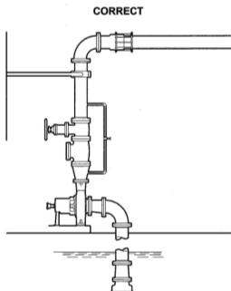
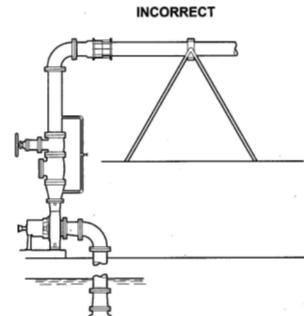
A.
Correct: sliding support does not retrain the piping to slide up/away B. Piping restrained (can
not slide up/away), high thermal expansion loads C. “Anchor”
will (problem!) allow pipe to expand towards/into the pump,
causing high axial loading
Figure 2 Rough alignment
phase (note that the motor and the pump are not coupled yet and the baseplate
is still sitting free, not grouted
Step 3
Once
you are satisfied with the rough alignment, remove all the equipment (pump, motor gearbox, etc) from the
baseplate. Level the baseplate to
maximum out of level of 0.025" (0.06 mm) from end to end in two
planes. Use machined pads as the base
for the leveling instruments. Inspect the foundation for cleanliness, and if
not clean, use solvent to remove grease and oil.
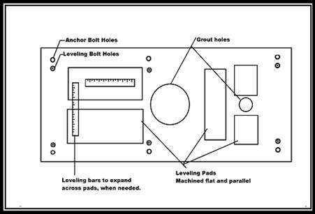
Figure 3 Baseplate
leveling pads and grout location
Step 4
Allow
time for the cleaning substances to evaporate.
Form the base using the appropriate techniques to allow for the weight,
temperature rise and fluidity of the grout material. Grout the base using epoxy grout. Allow the grout to cure, following the grout
manufacturer’s recommendations. This
normally requires 24 hrs at 80° F (27°C). Remove the forms and clean all sharp
residue and edges from the foundation.
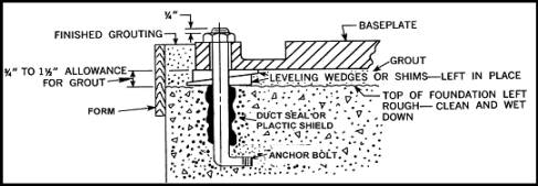
Figure 4 Typical
anchor bolt and leveling wedges
Step 5
The
rough alignment step, which we mentioned above, is critical to minimize the
changes that will be required to appropriately fit the piping to the pump. At the last stage, when the final spools are
installed, the final alignment will be achieved with small adjustments. This will minimize the adjustments required
on the motor feet/bolts. Unfortunately
(motor manufacturer’s take heed!), motor hold-down bolts are often too tight
and allow only for small adjustments to the motor before becoming bolt
bound. Motor manufacturers could improve
this situation significantly if motor feet were slotted, by design, rather than
drilled for bolts. Figure 5 shows
the tightness of space available to insert the foot hold-down bolt.
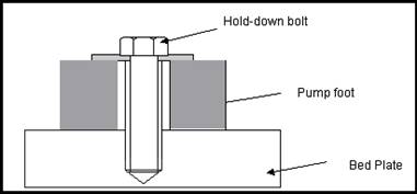
Figure 5 Potential
bolt-bound situation due to tight clearances between bolt, feet and base
This
illustrates once again why good alignment at step 3 can save time and the cost
of having to alter motor feet (a nightmare) by slotting or reaming.
Step 6
Reinstall
the pump and the motor on the baseplate.
Rough align the equipment again, using reverse indicator or laser
alignment or similar accurate techniques.
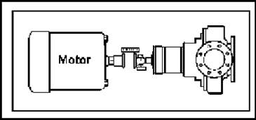
Figure 6 Rough alignment after grouting
It
should be now easy to fine-tune the motor movement within the allowable
alignment target without becoming bolt bound.
This is possible because of the rough alignment during the prior step (Step 4) was
completed. Note: Never install
shims under the pump feet. If the shims
are lost or misplaced then alteration to the piping may be required to get the
pump within the required alignment specification. The normal procedure is to place 0.125"
(3.2 mm) thick shims under the motor feet.
This allows for adjustments that will be required during final
alignment.
Step 7
Make
up the final spool pieces for the suction and discharge spaces. Bring the piping to the pump now.
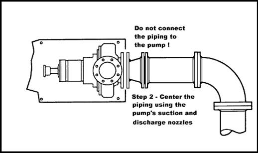
Figure 7 Illustration
of the final connection of the suction piping.
Step 8
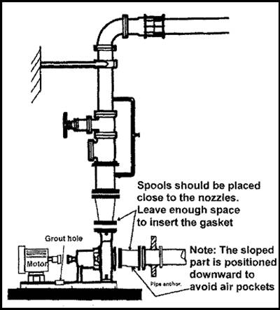
Warning! – “anchor” is placed erroneously - it will
restrain the pipe thermally moving away from the pump free: the pipe will
expand from the anchor into the pump! (see discussion
in Step 2)
Figure 8 Final piping
As
a final alignment step, bring the piping to the equipment; take final
measurements, tack weld the spools in place.
At this time the spools can be removed and taken back to the hot work
permit area to finalize the weld. Leave
a square and parallel gap between the flange faces. The gap should be wide enough to accommodate
the size of the gasket required, plus 1/16 - 1/8”, depending on piping sizing.
(This is the only distance over which the piping will be pulled. However,
because it is properly anchored before the spool pieces, this length is
short, and stresses are minimized).
Final align the equipment, taking into account hot and cold operating
conditions, using two indicators on the pump shaft coupling area.
Step 9
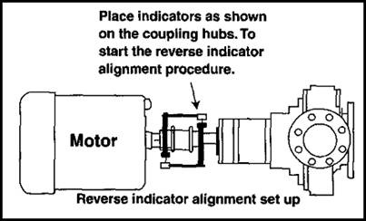
Figure 9 Overhead
view of the motor and pump
As
the piping is tightened into place, the shaft shall not be moved more than
0.002" (0.005 mm), otherwise modify the spool pieces until the piping
misalignment is fixed.
Several
clues are common to piping misalignment.
These clues come via the way of mechanical seal and or bearings running
hot, and failures. A quick analysis of
the failed parts can clearly show the evidence of piping misalignment. To make a final confirmation of the symptoms,
unbolt the piping while measuring the movement in the vertical and horizontal
plan. Again, the piping that moves more than
0.002" (0.005 mm) must be modified to correct the situation.
Step 10
Place
and indicator in horizontal and vertical planes, using the motor and pump
coupling.
Uncouple
the pump and motor, while watching the indicator movement. Start unbolting the flanges, and continue
watching for movement in the indicators.
If the needle jumps over 0.002" (0.005 mm) the piping has to be
modified to improve the pump’s performance.
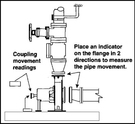
Figure 10 Piping
alignment verification
References
1.
1) Pump Standards, Hydraulic Institute publication, ANSI/HI 1.1‑1.5‑1994,
2.
2) API 610 Standard for centrifugal pumps, 8th Edition, American Petroleum
Institute, Washington, DC, August, 1995
3.
3) API 676 Standard for rotary pumps, 2nd Edition, American Petroleum
Institute,
4.
4) Equipment Testing Procedure for Centrifugal Pumps (Newtonian
liquids), 2nd Edition,
5.
5) AlChE Equipment Testing Procedure for Rotary positive displacement
pumps (Newtonian liquids), Second printing,
6.
6) Nelik L., "Centrifugal and Rotary Pumps: Fundamentals with
Applications", CRC Press,
7.
7) AlChE Equipment Testing Procedure, 1999,
8.
8) L. Rizo, L. Nelik,
“Piping-to-Pump Alignment”, Pumps & Systems, April 1999
E-Mail your questions and
suggestions to: