Article
#7: Lubrication Practices: How Grease-Lubricated Bearings Function
A
shielded, grease-lubricated ball bearing can be compared to a centrifugal pump
having the ball and-cage assembly as its impeller and having the annulus
between the stationary shield and the rotating inner race as the eye of the
pump.
Shielded
bearings are not sealed bearings. With the shielded type of bearing, grease may
readily enter the bearing, but dirt is restricted by the close fitting shields.
Bearings of the sealed design will not permit entry of new grease, whereas with
shielded bearings grease will be drawn in as the bearing cage assembly rotates.
The grease will then be discharged by centrifugal force into the ball track of
the outer race.
If
there is no shield on the backside of this bearing, the excess grease can
escape into the inner bearing cap of the equipment bearing housing.
Single-shield bearings
Plants
applying best-in-class-practices today consider the regular single shield
bearing with the shield facing the grease supply (Figure 7-1) to be the best
arrangement. Their experience indicates this simple arrangement will extend
bearing life. It will also permit an extremely simple lubrication and
relubrication technique if so installed.
This
technique makes it unnecessary to know the volume of grease already in the
bearing cartridge. The shield serves as a baffle against agitation. The
shield-to-inner-race annulus serves as a metering device to control grease
flow. These features prevent premature ball bearing failures caused by
contaminated grease and heat buildup due to excess grease. Further, warehouse
inventories of ball bearings can be reduced to one type of bearing for the
great bulk of existing grease-lubricated ball bearing requirements. For other
services, where an open bearing is a "must," as in some flush-through
arrangements, the shield can be removed in the field.
Figure 7-1 Single-shielded equipment bearing,
with the seal facing the grease cavity
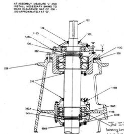
Double-shielded bearings
Some
manufacturers still subscribe to a different approach, having decided in favor
of double-shielded bearings. These are usually arranged as shown in Figure 7-2.
The housings serve as a lubricant reservoir and are filled with grease. By
regulating the flow of grease into the bearing, the shields act to prevent
excessive amounts from being forced into the bearing. A grease retainer
labyrinth is designed to prevent grease from reaching the inner side of the
bearing.
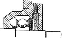
Figure 7-2 Double Shielded bearing with
grease. Metering plate facing the grease reservoir
On
equipment furnished with this bearing configuration and mounting arrangement,
it is not necessary to pack the housing next to the bearing full of grease for
proper bearing lubrication. However, packing with grease helps to prevent dirt
and moisture from entering. Oil from this grease reservoir can and does, over a
long period, enter the bearing to revitalize the grease within the shields.
Grease in the housing outside the stationary shields is not agitated or churned
by the rotation of the bearings and consequently, is less subject to oxidation.
Furthermore,
if foreign matter is present, the fact that the grease in the chamber is not
being churned reduces the probability of the debris contacting the rolling
elements of the bearing.
On
many pieces of equipment furnished with grease-lubricated double-shielded
bearings, the bearing housings are not usually provided with a drain plug. When
grease is added and the housing becomes filled, some grease will be forced into
the bearing. At this point any surplus grease will be squeezed out along the
close clearance between the shaft and the outer cap because the resistance of
this path is less than the resistance presented by the bearing shields,
metering plate, and the labyrinth seal.
Open bearings
High-load
and/or high-speed bearings are often supplied without shields to allow cooler
operating temperature and longer life. One such bearing is illustrated in
Figure 7-3.
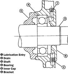
Figure 7-3 High load/ high speed bearings are
often supplied without shield
If
grease inlet and outlet ports are located on the same side, this bearing is
commonly referred to as "conventionally grease lubricated." If grease
inlet and outlet ports are located at opposite sides, we refer to
"cross-flow lubrication." Figure 7-4 shows a cross-flow lubricated
bearing.
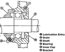
Figure 7-4 Open bearing with cross flow
grease lubrication
Lifetime lubricated,
"sealed" bearings
Lubed
for-life bearings incorporate close-fitting seals in place of, or in addition
to shields. These bearings are customarily found on low horsepower equipment or
on appliances, which operate intermittently.
Although
a large petrochemical company in West Virginia has expressed satisfaction with
sealed ball bearings in certain equipment applications as long as bearing
operating temperatures remained below 150o C. (300o F) and speed factors DN (mm
bearing bore times revolutions per minute) did not exceed 300,000. Close-fitting
seals can cause frictional heat and that loose fitting seals cannot effectively
exclude atmospheric air and moisture, which will cause grease deterioration.
Procedures for Re-Greasing
Equipment Bearings
Rotating
equipment bearings should be re-greased with grease, which is compatible with
the original charge. It should be noted that the polyurea greases often used by
the equipment manufacturers may be incompatible with lithium base greases.
Single-Shielded Bearings
To
take advantage of single-shield arrangements, Phillips Petroleum developed
three simple recommendations:
1.
Install a single-shield ball bearing with the shield facing the grease supply
on equipment having the grease fill and-drain ports on that same side of the
bearing. Add a finger full of grease to the ball track of the backside of the
bearing, during assembly.
2.
After assembly, the balance of the initial lubrication of this single-shielded
bearing should be done with the equipment idle. Remove the drain plug and pipe.
With a grease gun or high volume grease pump, fill the grease reservoir until
fresh grease emerges from the drain. The fill and drain plugs should then be
reinstalled and the equipment is ready for service.
It
is essential that this initial lubrication not be attempted while the equipment
is running. It was observed that to do so would cause, by pumping action, a
continuing flow of grease through the shield annulus until the overflow space
in the inner cartridge cap is full. Grease will then flow down the shaft and
into areas where it is not wanted. This will take place before the grease can
emerge at the drain.
3.
Relubrication may be done while the equipment is either running or
idle.
(It should be limited in quantity to a volume approximating one-fourth the
bearing bore volume.) Test results showed that fresh grease takes a wedge-like
path straight through the old grease, around the shaft, and into the ball
track. Thus, the overflow of grease into the inner reservoir space is quite small
even after several relubrications. Potentially damaging grease is thus kept
from the stator winding, in motors. Further, since the ball and cage assembly
of this arrangement does not have to force its way through a solid fill of
grease, bearing heating is kept to a minimum. In fact, it was observed that a
maximum temperature rise of only 20 o F. occurred 20 minutes after the grease
reservoir was filled. It returned to 5 o F rise two hours later. In contrast,
the double-shield arrangement caused a temperature rise of over 100 o F (at 90
o F ambient temperature the resulting temperature was 190 o F.) and maintained
this 100 o F rise for over a week.
Double-Shielded Bearings
1. Ball Bearings
A. Pack (completely fill) the cavity adjacent
to the bearing. Use necessary precautions to prevent contaminating this grease
before equipment is assembled.
B. After assembly, lubricate stationary
equipment until a full ring of grease appears around the shaft at the relief
opening in the bracket.
2. Cylindrical Roller
Bearings
A. Hand pack bearing before assembly.
B. Proceed as outlined in (1) and (2) for
double shielded ball bearings.
If
under-lubricated after installation, the double shielded bearing is thought to
last longer than an open (non-shielded) bearing given the same treatment
because of grease retained within the shields (plus grease remaining in the
housing from its initial filling).
If
over-greased after installation, the double-shielded bearing can be expected to
operate satisfactorily without overheating. This will be as long as the excess
grease is allowed to escape through the clearance between the shield and inner
race, and the grease in the housing adjacent to the bearing is not churned,
agitated and caused to overheat.
It
is not necessary to disassemble equipment at the end of fixed periods to grease
bearings. Bearing shields do not require replacement.
Double-shielded
ball bearings should not be flushed for cleaning. If water and dirt are known
to be present inside the shields of a bearing because of a flood or other
circumstances, the bearing should be removed from service.
All
leading ball-bearing manufacturers are providing reconditioning service at a
nominal cost when bearings are returned to their factories. As an aside,
reconditioned ball bearings are generally less prone to fail than are brand new
bearings. This is because grinding marks and other asperities are now burnished
to the point where smoother running and less heat generation are likely.
Open Bearings
Equipment
with open, conventionally greased bearings is generally lubricated with
slightly different procedures for drive-end and opposite end bearings.
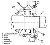
Figure 7-5 Double-Shielded Bearings
1. Lubrication procedures for drive-end bearings
A. Relubrication with the shaft stationary is
recommended. If possible, the equipment should be warm.
B. Remove plugs and replace with grease
fitting.
C. Remove large drain plug when furnished
with the equipment.
D. Using a low pressure, hand operated grease
gun, pump in the recommended amount of grease, or use 1/4 of bore volume.
E. If purging of system is desired, continue
pumping until new grease appears either around the shaft or at the drain
opening. Stop after new grease appears.
F. On large equipment provisions have usually
been made to remove the outer cap for inspection and cleaning. Remove both rows
of cap bolts. Remove, inspect and clean cap. Replace cap, being careful to
prevent dirt from getting into bearing cavity.
G. After lubrication allow the equipment to
run for fifteen minutes before replacing plugs.
H. If the equipment has a special grease
relief fitting, pump in the recommended volume of grease or until a one-inch
long string of grease appears in any one of the relief holes. Replace plugs.
I. Wipe away any excess grease which has
appeared at the grease relief port.
2. Lubrication procedure for bearing opposite drive end
If bearing hub is accessible, as in smaller
equipment with large couplings or drip-proof equipment, follow the same
procedure as for the drive end bearing. For fan-cooled equipment note the
amount of grease used to lubricate shaft end bearing and use the same amount
for commutator-end bearing.
Motor
bearings with grease inlet and outlet ports on opposite sides, are called
cross-flow lubricated. Regreasing is accomplished with the equipment running.
The following procedure should be observed:
2.1.
Start equipment and allow to operate until normal equipment temperature is
obtained.
2.2
Inboard bearing (coupling end):
A. Remove grease inlet plug or fitting.
B. Remove outlet plug. Some equipment designs
are equipped with excess grease cups located directly below the bearing. Remove
the cups and clean out the old grease.
C. Remove hardened grease from the inlet and
outlet ports with a clean probe.
D. Inspect the grease removed from the inlet
port. If rust or other abrasives are observed, do not grease the bearing. Tag
equipment for overhaul.
E. Bearing housings with outlet ports: (1)
insert probe in the outlet port to a depth equivalent to the bottom balls of
the bearing; (2) replace grease fitting and add grease slowly with a hand gun.
Count strokes of gun as grease is added; and (3) stop pumping when the probe in
the outlet port begins to move. This indicates that the grease cavity is full.
F. Bearing housings with excess grease cups:
(1) replace grease fitting and add grease slowly with a handgun. Count strokes
of gun as grease is added and (2) stop pumping when grease cavity is full.
3. Outboard bearing (fan end):
a.
Follow inboard bearing procedure provided the outlet grease ports or excess
grease cups are accessible,
b.
If grease outlet port or excess cup is not accessible, add 2/3 of the amount of
grease required for the inboard bearing.
c.
Leave grease outlet ports open-do not replace the plugs. Excess grease will be
expelled through the port.
d.
If bearings are equipped with excess grease cups, replace the cups. Excess
grease will expel into the cups.
Lev
Nelik
Pumping
Machinery, LLC
Some additional feedback from the professionals
in the field:
Roy A. Forson, CLS
Maintenance Manager
Imerys Performance Minerals :
Type A: The proper bearing re-lubrication with a drain plug is:
- Check
Temperature
- Wipe
grease fitting
- Remove
purge plug and clean out hard grease (unit must be down. If you cannot
take the top cap off, then insert small spoon-type tool and feel for hard
grease. If no hard grease is found, then continue below.
- Check
seals for excessive grease (blown seals, cracked seals. These should be
replaced)
- Pump
new grease until new grease exits out of the purge plug drain.
- Run
unit with purge plug removed for 10-30 minutes. (This will allow the
grease to equalize)
- Clean
and replace the purge plug.
Type B: The proper bearing re-lubrication without a drain plug
is:
- Check
temperature
- Shut
down & immediately remove grease fitting to allow the bearing to
self-purge
- Clean
and replace the fitting
- Pump
a limited quantity of grease to avoid rupturing the grease seal
- Remove
the fitting and allow for equalization
- Repeat
until grease comes out
- Replace
grease fitting
Type C: The proper bearing re-lubrication with a relief fitting
is:
- Check
temperature
- Clean
fitting and pump grease until it relieves
- If
it doesn't relieve, fitting may be plugged. Remove and replace
- Run
and check for relief/temperature
Additional general considerations for re-lubrication
of bearings other than electric motor bearings:
(Remember,
if you are not going to use any calculation for re-greasing, then you are
guessing)
1. If unit is running, check
temperature of all bearing surfaces. It is important to know if it's running
hot.
2. Using all safety precautions,
locate grease fitting and clean the fitting of debris by wiping it off with a
clean rag.
3. Verify the type of grease in the
grease gun - do not take for granted that what is marked on the pump is what's
in the pump.
4. Pump a little bit of grease out of
the gun and wipe the end. This will remove any debris trapped in the nozzle
5. Install the end of the grease
nozzle onto the grease fitting and verify it is on properly
6. Pump grease into the bearing based
on the plant "grease amount" recommendations.
Caution - if grease will not
pump into the bearing, the grease fitting is probably bad (check valve probably
stuck)
7. Observe the seal of the bearing
and be sure not to over-grease. Over-greasing will cause the seal to open,
consequently breaking the seal.
8. After greasing, listen for any
unusual sounds.
There are more technical instructions for the serious user like calculating re-lubrication
amounts based on bearings size, re-greasing frequencies based on bearing size,
speed, conditions, etc.
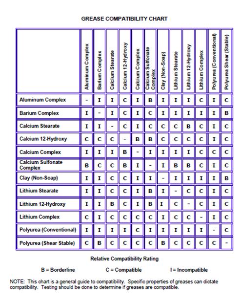
Know the thickener type. If grease tube mentions polymers - these are additives that can improve things
like increase base oil viscosity and increase adhesiveness and really have
little to do with compatibility. The thickener type is most important. Some
thickeners are not compatible with others. For example, aluminum is not
compatible with lithium, polyurea is not compatible with most thickeners,
barium, clay, calcium thickeners are not compatible with other types. Some of
the complex mixes are compatible, but you really have to know what it is your
are commingling. My advice is to conduct a compatibility test in a lab. Also,
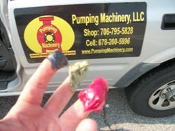
when mixing two incompatible thickeners, you may get one of two typical reactions
- a soft and soupy solution where the grease does not stay put, or you can get
a rock hard material in the bearing housing. This occurs when the oil leeches
from the grease and all that remains is the thickener.
Additionally, remember grease is comprised of three components -
base oil, thickener, and additives. 85% of the three components is oil so it's
important to know what type of oil is being used, mainly synthetic.
Sorry to be long winded, but most places I use to go to have no
idea of the differences in greases. In many cases, a salesman will try to sell
you something and tell you it's compatible, but he really may not know.
Roy A. Forson, CLS
Maintenance Manager
Imerys Performance Minerals

To learn more about this topic, e-mail your comments to us at: