 Pump
Magazine On-Line
Pump
Magazine On-Line

INDUSTRIAL DIGEST
|
INDUSTRIAL DIGEST
|
|
|
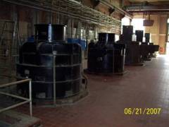
ARTICLE #42: TRANSIENT START-UP PROBLEMS FOR PUMPS WITH SYNCHRONOUS MOTORS A large wastewater processing plant experienced continual problems with its influent raw wastewater pumps for several years. These pumps are rated at 70,000 gpm, 24 feet head, and driven by 500 hp, 4000 volts, 225 rpm Westinghouse brushless synchronous motors, 57.5 amps steady state rated current.
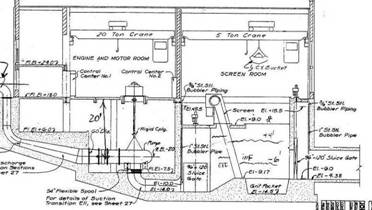
As shown on the drawing below, influent water level varies between EL=-6’ and EL=+4’. Pump volute/impeller centerline is at elevation EL=-2’, and impeller tips barely touch the water at elevation EL=-4’. The issue reported by operators was difficulty starting these units (tripping on high amps) at high water levels (with impellers flooded), but no trips at low flow levels (impellers dry), although then pumps would have trouble catching prime.
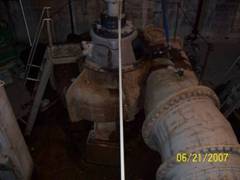
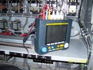
Pumping Machinery Company was requested to troubleshoot these units to identify the source of the problem and recommend corrective actions. Since the main issue reported was difficulty starting pump flooded, a radial hydraulic thrust, or high power (low head at initially unfilled conduit) were initially suspected as a root cause. However, after extensive review of pump hydraulics, it was determined that horsepower is non-overloading across the entire curve, and hydraulic radial thrust is not excessive for the design. There were no signs or sound of internal rubbing or any other mechanical pump related abnormalities. A more likely possibility appeared to be motors or motor controls. Synchronous motors have certain advantages over asynchronous, but are more complicated, particularly with regard to controls. The way a synchronous motor starts is as follows. Initially, it operates as a typical induction (asynchronous) motor, with magnetic field induced within the rotor armature by the rotating stator field. As rotor accelerates and approaches close to synchronous speed, a field DC voltage is applied by controls to the rotor (typically via brushes), at which point rotor pulls into synchronism. For these motors, exciter (rotor field) coils current is 37.7 amps at 125 Volts field DC voltage. The timing of the rotor field application is critical, typically around 95% of the synchronous speed. To pinpoint the root cause, a detailed transient analysis study of the start-up was conducted. Motor amps, volts and DC field volts were recorded by the clamp-on power meter, with graphics capability via download to a PC computer. Amps were taken from the CT (60:1 ratio) transformers and volts from the VT (35:1 ratio) transformers.
Fig. 1 Start-up test #1 with partially flooded impeller, EL=-1.5’, i.e. water above impeller centerline. Main amps and volts plotted. Motor trips after about 5 seconds on high amps As can be seen from Fig. 1, after completing normal locked rotor amps swing to 390 amps (390/57.5 = 6.8 times, which is not unusual), the rotor is having trouble to synchronize, both amps and volts begin to swing wildly, until controls trip the unit on high amps after set time.
Fig. 2 Start-up test #2 (dry impeller, EL = -3.5’). Motor pulls to synchronous speed after about 3 seconds Dry-pump start-up traces look similar to wet-pump start-up #1, with amps and volts fluctuating wildly also, but somehow the rotor eventually manages to get close to synchronous speed and does not trip. The pump, however, remains dry, unable to catch prime. The unit is re-started again, but this time field DC volts are also recorded and plotted:
Fig. 3 Main amps and field DC volts begin to reveal what is going on Per Fig. 3, a start button is pushed at time t=11.56.6 sec, and rotor field DC is applied at t=11.57.0 sec, i.e. 0.4 seconds after start-up. At low water level, dry rotor accelerates quickly, unburden by the additional inertia of the water mass. Despite field DC voltage applied prematurely, which causes wild fluctuation of amps, the rotor approaches and pulls into synchronous speed quickly (within less then 3 seconds), before the control timer would trip otherwise. In contrast (Fig. 2, wet rotor), impeller, surrounded and filled by water, is prevented from accelerating quickly, and thus tripped by timers on high amps before the motor RPM approaches close to synchronous speed. Once transient behavior was understood, corrections to the controls were made, mainly by applying DC volts 5 seconds after start-up, instead of initial setting of 0.4 seconds.
Fig.4a Start-up test #4 (correct application of the DC field) Swings of amps are now essentially gone, with rotor pulling to synchronous speed when it is close to 95% of the synchronous speed.
Fig. 4b Stable behavior of the main windings amps and volts. With the corrective action applied to controls, pumps now operate well, with no start-up trouble. As always, a quiz question to our readers: is there one more important test missing to prove the point more definitely? (Hint: examine steady-state amps).
Dr. Lev Nelik, P.E., APICS Pumping Machinery, LLC Pump School Training Services
|